
Ch340g esp8266 wifi driver download windows 7 - sorry, that
Ks0173 keyestudio Nano ch340
Introduction
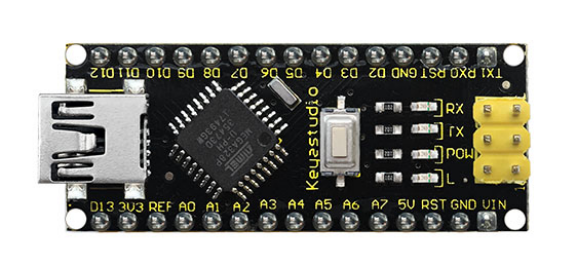
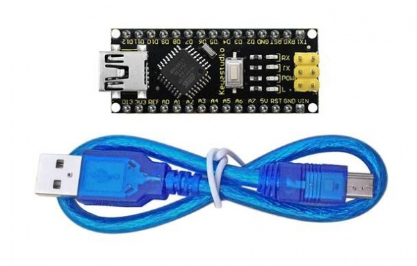
keyestudio Nano CH340 is a small, complete, and breadboard-friendly board based on the ATmega328P-AU. Compared with ARDUINO NANO, the USB-to-serial port chip used in keyestudio Nano is CH340G, so that the using method is the same except the driver installation file.
It has 14 digital input/output pins (of which 6 can be used as PWM outputs), 8 analog inputs, a 16 MHz crystal oscillator, a mini USB port, an ICSP header and a reset button.
Note that ICSP (In-Circuit Serial Programming) header is used to program the firmware to ATMEGA328P-AU, but generally the chip has been preburned before leave the factory. So use it less.
The keyestudio Nano can be powered via the Mini-B USB connection, or female headers Vin/GND (DC 7-12V).
Specification
| Microcontroller | ATmega328P-AU |
|---|---|
| Operating Voltage | 5V |
| Input Voltage (recommended) | DC7-12V |
| Digital I/O Pins | 14 (D0-D13) (of which 6 provide PWM output) |
| PWM Digital I/O Pins | 6 (D3, D5, D6, D9, D10, D11) |
| Analog Input Pins | 8 (A0-A7) |
| DC Current per I/O Pin | 40 mA |
| Flash Memory | 32 KB of which 2 KB used by bootloader |
| SRAM | 2 KB |
| EEPROM | 1 KB |
| Clock Speed | 16 MHz |
| LED_BUILTIN | D13 |
Element and Interfaces
Here is an explanation of what every element and interface of the board does: 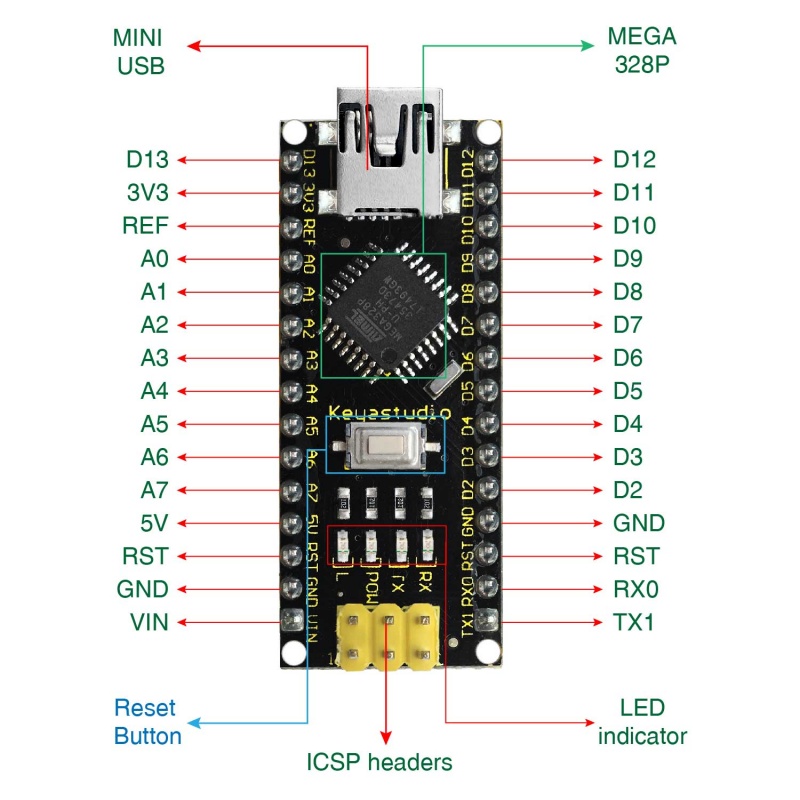
| 1 | ICSP Header | ICSP (In-Circuit Serial Programming) Header ICSP is the AVR, an micro-program header consisting of MOSI, MISO, SCK, RESET, VCC, and GND. It is often called the SPI (serial peripheral interface) and can be considered an "extension" of output. In fact, slave the output devices under the SPI bus host. |
| 2 | LED indicator(RX) | Onboard you can find the label: RX(receive ) When control board communicates via serial port, receive the message, RX led flashes. |
| 3 | LED indicator(TX) | Onboard you can find the label: TX (transmit) When control board communicates via serial port, send the message, TX led flashes. |
| 4 | LED indicator(POW) | Power up the control board, LED on, otherwise LED off. |
| 5 | LED indicator(L) | There is a built-in LED driven by digital pin 13. When the pin is HIGH value, the LED is on, when the pin is LOW, it's off. |
| 6 | RX0(D0)TX1(D1)D2-D13 | It has 14 digital input/output pins D0-D13 (of which 6 can be used as PWM outputs). These pins can be configured as digital input pin to read the logic value (0 or 1). Or used as digital output pin to drive different modules like LED, relay, etc. |
| 7 | RST | Reset pin: connect external button. The function is the same as RESET button. |
| 8 | MEGA 328P | Each board has its own microcontroller. You can regard it as the brain of your board. Microcontrollers are usually from ATMEL. Before you load a new program on the Arduino IDE, you must know what IC is on your board. This information can be checked at the top surface of IC. |
| 9 | MINI USB | The board can be powered via Mini-B USB connection. Also upload the program to the board via USB port. |
| 10 | 3V3 pin | rovides 3.3V voltage output |
| 11 | REF | Reference external voltage (0-5 volts) for the analog input pins. Used with analogReference(). |
| 12 | A0-A7 | The Nano has 8 Analog Pins, labeled A0 through A7. |
| 13 | 5V pin | Provides 5V voltage output |
| 14 | GND | Ground pin |
| 15 | VIN | Input an external voltage DC7-12V to power the board. |
| 16 | Reset Button | Used to reset the control board |
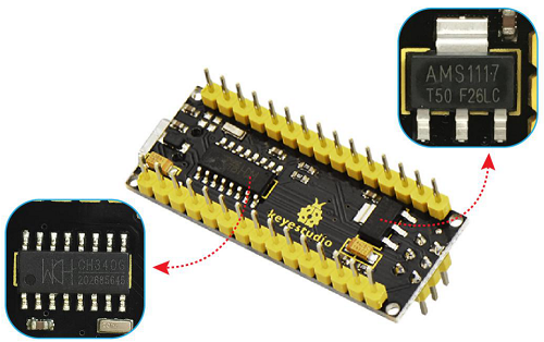
| 17 | CH340G | USB-to-serial port chip, converting the USB signal into Serial port signal. |
| 18 | AMS1117 | Convert the external voltage input DC7-12V into DC5V, then transfer it to the processor and other elements. |
Specialized Functions of Some Pins
- Serial communication: 0 (RX) and 1 (TX). Used to receive (RX) and transmit (TX) TTL serial data.
- PWM (Pulse-Width Modulation): D3, D5, D6, D9, D10, D11
- External Interrupts: D2 (interrupt 0) and D3 (interrupt 1). These pins can be configured to trigger an interrupt on a low value, a rising or falling edge, or a change in value. See the attachInterrupt() function for details.
- SPI communication: D10 (SS), D11 (MOSI), D12 (MISO), D13 (SCK).
- IIC communication: A4 (SDA); A5(SCL)
Windows System
Download the Arduino IDE
When getting this control board, we need to install Arduino IDE.
Enter the website https://www.arduino.cc/,click and
and 
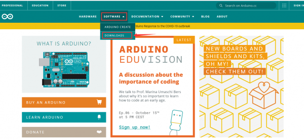
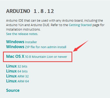
Select versions you want to download, the latest version could be downloaded.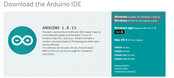
Alternatively, you could select previous release.
In this project, we use 1.8.12 version.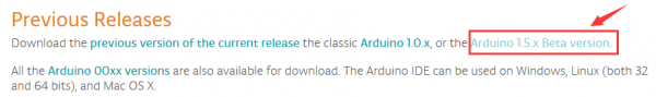
Click to view the below page
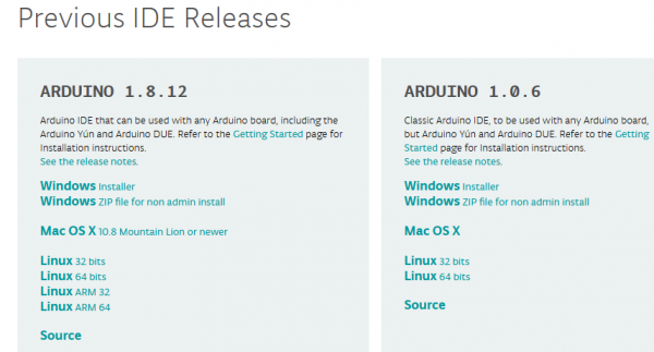
Click  to download an installer of Arduino 1.8.12 version,which needs to be installed manually. When you tap
  a zip file of Arduino 1.8.12 version will be directly downloaded, and you only need to unzip it to finish installation.
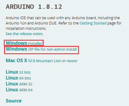
Click icon to download Arduino IDE.
Download Driver of CH340
https://fs.keyestudio.com/CH340-WIN
Installing the Driver
The driver will be installed after downloading Arduino IDE.
If your system is Windows 10, the computer will automatically install driver.
For other systems, like Windows7, we need to install driver manually.
The USB to serial chip of control board is CH340G, therefore, we will install the driver(usb_ch341_3.1.2009.06) for it.
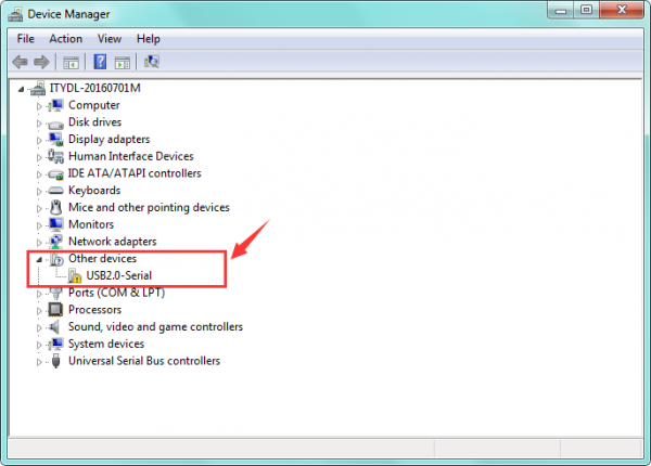
Connect control board to computer with USB cable.
Click Computer----- Properties----- Device Manager, as shown below:
Then right-click on the device and select the top menu option (Update Driver Software...) shown as the figure below. 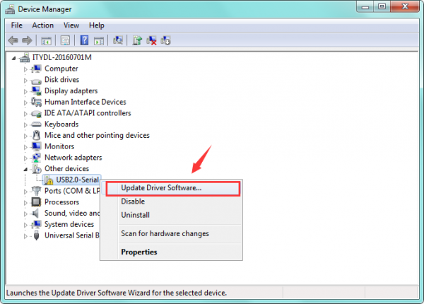
Then it will be prompted to either “Search Automatically forupdated driversoftware” or “Browse my computer for driver software”. Shown as below. In this page, select “Browse my computer for driver software”. 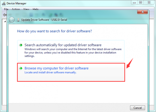
After that, select the option to browseand navigate to the “drivers” folder of usb-ch341 installation. 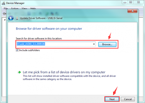
Once the software has been installed, you will get a confirmation message. Installation completed, click “Close”. 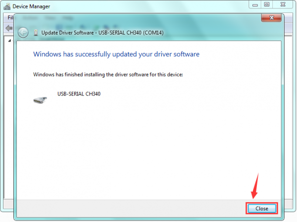
Up to now, the driver is installed well. Then you can right click “Computer” —>“Properties”—>“Device manager”, you should see the device as the figure shown below. 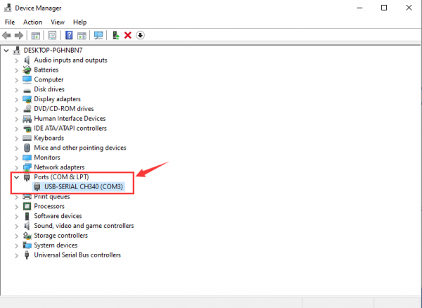
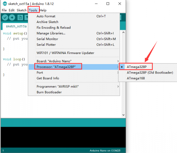
Select the Arduino Board
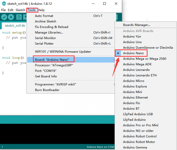
Open the Arduino IDE, you’ll need to click the “Tools”, then select the Board that corresponds to your Arduino. 
Setting IDE for new bootloader
Arduino Nano board could burn new and old bootloader. New bootloader is only compatible with 1.8.9 IDE and above. Yet the old one is compatible with all versions.
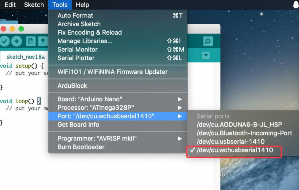
Select your serial port
Select the serial device of the Arduino board from the Tools | Serial Port menu.
Note: to avoid errors, the COM Port should keep the same as the Ports shown on Device Manager. 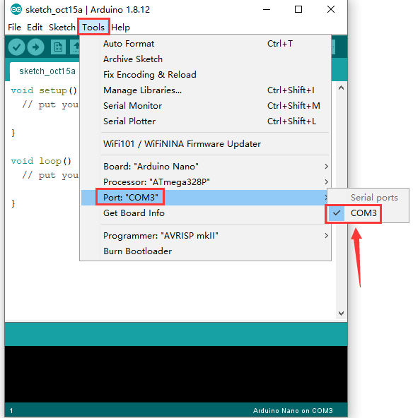
Hello World!
Copy the following code in the Arduino IDE.
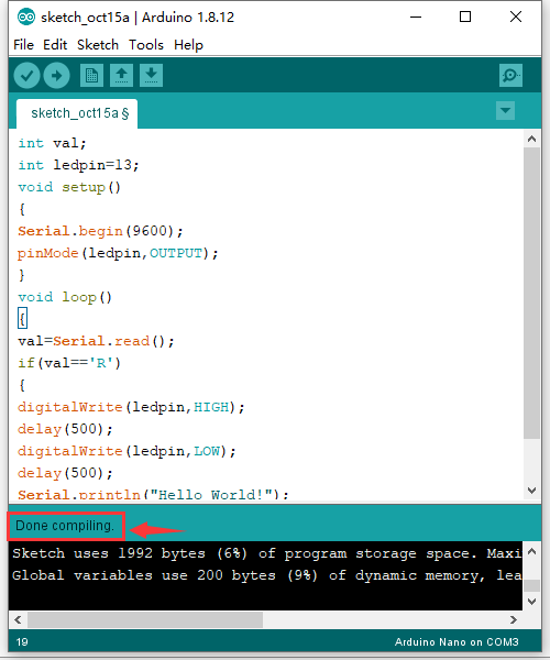
int val; int ledpin=13; void setup() { Serial.begin(9600); pinMode(ledpin,OUTPUT); } void loop() { val=Serial.read(); if(val=='R') { digitalWrite(ledpin,HIGH); delay(500); digitalWrite(ledpin,LOW); delay(500); Serial.println("Hello World!"); } }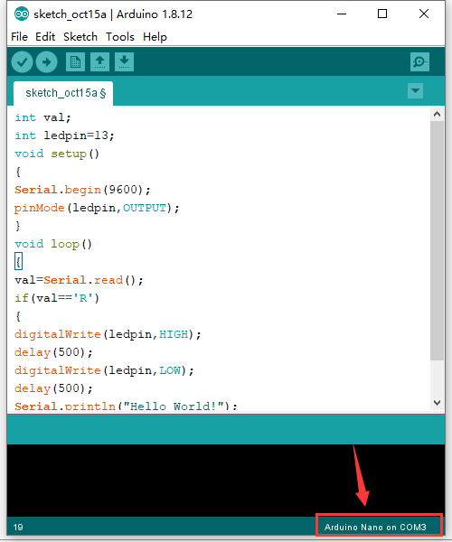
Then click verify button to check the errors. If compiling successfully, the message "Done compiling." will appear in the status bar. 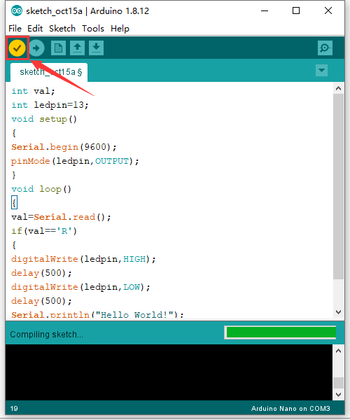
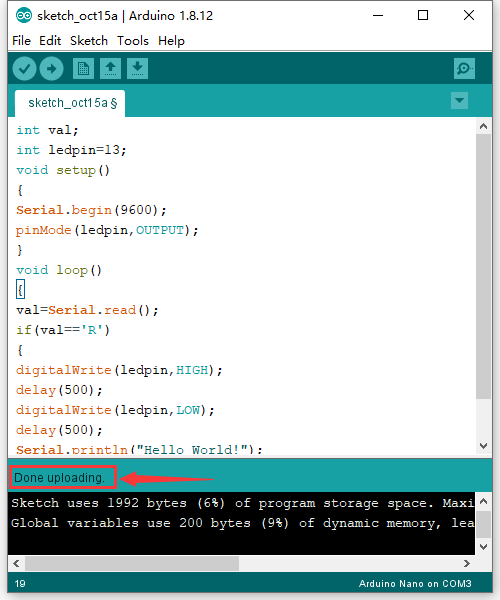
After that, click the “Upload” button to upload the code. If the upload is successful, the message "Done uploading." will appear in the status bar. 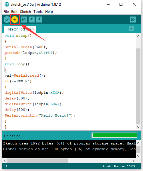
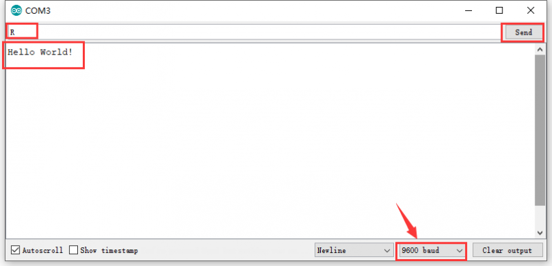
Then click  to open serial monitor and set the baud rate to 9600, enter an “R” and click Send, that is, the computer will send the character R. When NANO board receives it, you should see the RX led on the board flash once, and then D13 led flash once; when keyestudio NANO board sends "Hello World!" to the computer, finally you should see the "Hello World!" is showed on the monitor, and TX led on the board flash once.
MAC System
Install Arduino IDE on MAC System
The installation instruction is as same as the chapter 5.1, as shown below:
Download Driver of CH340
https://fs.keyestudio.com/CH340-MAC
How to Install Driver of CH340
Please refer to the following link: https://wiki.keyestudio.com/Download_CH340_Driver_on_MAC_System
Setting Arduino IDE
The setting method is as same as the chapter 5.6 except from COM port, as shown below:
Package Included
- Keyestudio NANO ch340 * 1pcs
- 30cm mini USB cable * 1pcs
Resource Links
https://fs.keyestudio.com/KS0173
Troubleshooting
If you have problems, please see the troubleshooting suggestions.
Get One Now

-